


Box girder bridges
Steel box girders and steel and concrete composite box girders are used for long spans, where the self weight of the bridge needs to be minimized, and for situations where their excellent high torsional stiffness is of particular benefit. The clean lines of box girders bridges, usually with no visible external stiffening, is generally considered to give a excellent appearance and durability, since there are no traps for dirt and moisture. This article illustrates a few examples of box girder construction for bridges.
Box sections are also sometimes used as compression members, such as in towers of cable-supported structures or arch structures, but these applications are outside the scope of this article.

[top]Forms of construction
A box girder bridge is one in which the principal structural element is one or more closed cells, acting in bending. Box girders are used for highway bridges, railway bridges and footbridges – different structural forms are chosen for each of these applications.
[top]Highway bridges
[top]Composite box girders

For highway bridges, the structural configuration is usually of a reinforced concrete deck slab, carrying the traffic, on top of steel girders. The deck slab acts compositely with the steel girders.
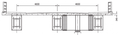
For spans in the range 45 to 100m, multiple girders are used, with the slab spanning transversely between the webs. For such configurations, relatively narrow rectangular steel box sections have sometimes been chosen, as shown right. However, such sections are rather small and introduce significant hazards for access for construction and maintenance and are rarely chosen now for this span range.

M25/M4 Junction 4B Bridges

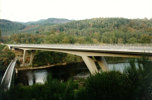
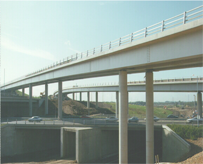
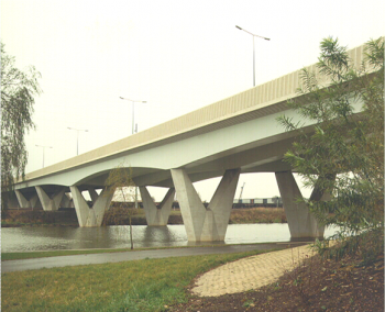
An alternative configuration that is now more commonly used employs ‘open topped’ trapezoidal girders. These girders have a steel bottom flange, inclined steel webs and a narrow steel flange on top of each web. The closed cell is formed by the reinforced concrete deck slab. This form is shown right. With this configuration, material access during construction can be minimised by the use of permanent formwork (or precast slabs) and for maintenance the cells are larger than those for rectangular steel boxes, thus reducing the difficulties of access.
With both forms, the girder depth is usually uniform at the lower end of the span range, but variable depth girders are used for longer spans. With ‘trapezoidal’ sections, this results in a variation of the width of the bottom flange, as shown below.
The deck slab is of nominally uniform thickness, about 250 mm thick. This limits the transverse spacing of webs to about 4m.
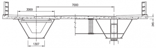
An alternative form used in continental Europe is a single cell trapezoidal cell steel girder with a transversely prestressed deck slab. The slab is deeper over the webs of the girder, allowing the transverse span of the slab to be up to 7m.
For longer spans, twin girders (usually rectangular cross section) with cross girders and cantilever girders are often used. This allows two girders to support wide decks (dual carriageway roads). With those longer spans the girders are very often variable depth.
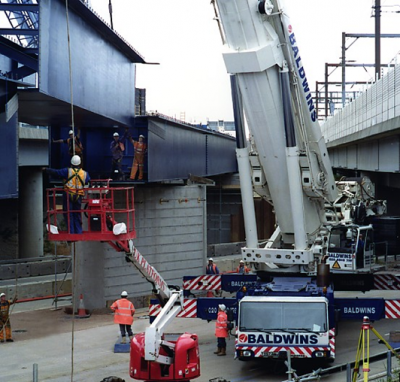
Open trapezoidal composite box girder during construction
Variable depth trapezoidal box girders
River Nene Bridge, Peterborough


[top]Steel box girders
For spans over about 200m, all steel construction is often used. The roadway is then carried on a longitudinally stiffened steel top flange, commonly known as an orthotropic steel deck. Such construction is lighter but is more complex to fabricate.


Foyle Bridge, Londonderry
[top]Cable-supported box girders
For very long spans, cable stayed construction is often used in conjunction with steel or composite box girders. Steel box girders are also used as stiffening girders of suspension bridges. For such applications an ‘aerodynamically shaped’ cross section profile is used.
[top]Curved bridges
Where the road is curved in plan, box girders can be curved to suit, which ensures that the cantilevers are of constant length.
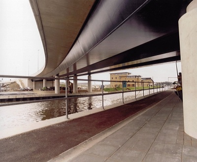

Fossedyke Bridge, Lincoln
[top]Railway bridges

For railways, construction depth is usually very tightly constrained and half through construction must be employed. One option is then the Network Rail ‘Standard Box Girder’.
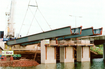
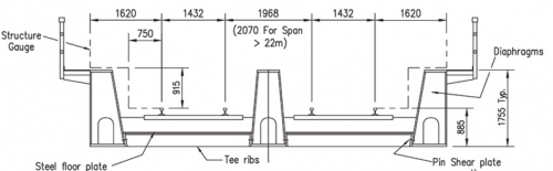
The Network Rail Standard Box Girder type bridge that covers a span range from 21m to 39m uses trapezoidal box girders with a transverse ribbed steel deck spanning between notionally pin-jointed shear plate connections: the box girders are stabilised by linear rocker bearings. This design is particularly suited to piecemeal crane erection during track possession. With half through construction, the deck can be either in situ concrete, partially encasing close centred cross girders, or a normal slab above more widely spaced cross girders. Stiffened steel plate construction can also be used, depending on the proposed erection method and available construction depth.
For railways on new alignments, where construction depth may not be so tightly constrained, the track can be carried on a slab-on-beam composite bridge, in the same way as used for highways. The use of box girders is then particularly advantageous as their greater torsional stiffness reduces susceptibility to track twist.

M20 Newington Bridge
[top]Footbridges

Box girders are usually considered for footbridges only for spans over about 30m, and most box girder footbridges adopt an all-steel configuration. The advantage in using an all-steel configuration is that the whole cross section, including parapets, can be fabricated at the works for delivery and erection in complete spans; the weight of such spans is modest and easily handled by a mobile crane. The thickness of the top flange which also forms the floor plate will be determined by overall bending strength rather than local floor loading. The plate is typically supported by transverse stiffeners which cantilever to edge beams. Two or three longitudinal stiffeners may be provided to stiffen the floor plate when acting as the compression flange of the box. Diaphragms are needed at supports and are often provided at several positions along the length of the girder (typically the third points) to control distortion. Large holes will be required in the diaphragms if access is required during fabrication or maintenance.

[top]Design aspects

The selection of a box girder form usually results in relatively thin plate panels (in terms of thickness to width ratio) for the webs and bottom flanges (and for top flanges, in all-steel boxes). Avoidance of local buckling in compression zones and in shear requires appropriate stiffening and longitudinal stiffeners are often required. Although box sections offer high torsional stiffness, internal cross frames are usually needed to prevent distortion (when one web is subject to greater shear than the other, one diagonal dimension across the cell increases and the other decreases). Bearings at supports are normally within the width of the bottom flange (rather than directly under the webs) and an internal diaphragm is needed to transfer the reactions.
When open-top boxes are used, they have very little torsional stiffness at the bare steel stage and the narrow top flanges might be susceptible to lateral buckling (a later-torsional buckling mode for the U-shaped section). It is therefore necessary to introduce some plan bracing to the top flange (not necessarily over the full lengths of the spans) to restrict twist and slenderness for buckling. Such bracing must avoid conflict with slab construction.
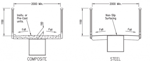
For any closed cell that requires internal access to construct it or to carry out inspection and maintenance, Health and safety considerations require sufficiently large and well-placed openings that an injured person could be quickly evacuated. All internal stiffening and diaphragms must therefore be designed such that openings are big enough and that movement along the cell is unimpeded. The following design aspects are discussed in Guidance Note 1.08:
- Complexity of fabrication
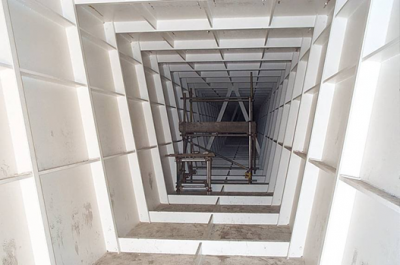
- Internal access
- Stability during construction
- longitudinal stiffening of plate panels
- Transverse stiffeners and beams
- Control of distortion
- Web/flange welds
Guidance on design of composite highway bridges is given in SCI P140 (although the main design standard referred to in that publication is BS 5400-3[1], the principles are equally applicable to design to the Eurocodes).
Guidance on the design of railway bridges is given in SCI P318. Design requirements for the Network Rail Standard Box Girder bridge are given in documents available from Network Rail.
[top]Construction and maintenance aspects
All the features of stiffening and diaphragms mentioned above lead to more complex fabrication, without the advantage of the semi-automatic processes that can be employed with I-section girders, and thus to more costly fabrication. This is particularly true for steel decks: the fabrication of orthotropic decks requires much experience and special welding procedures in order to achieve the necessary tolerances on flatness.
For composite bridges, the use of temporary formwork to construct the slab would in most cases lead to difficult and hazardous work inside the girders and thus permanent formwork (or possibly full thickness precast slab units) is almost always used.
To avoid a continuing requirement to maintain an internal corrosion protection system over the life of a bridge, it is now common practice to use weathering steel for the box girders, even when an external coating system is specified (either for corrosion protection or appearance).
Externally, there are very few features on box girders that can accumulate dirt and moisture; this should ensure good durability for either a coating system or a weathering steel surface. If a coating system is applied, maintenance is easier with the clean surfaces of the girders.
[top]Why choose steel box girders?
The selection, or otherwise, of a steel box girder always needs a consideration of the relative advantages and disadvantages of box girder elements compared to the more traditional 'I' girder elements.
Advantages, compared to 'I' girders:
- High torsional stiffness and strength, giving greater suitability for horizontally curved bridges, greater aerodynamic stability and reduced susceptibility to lateral buckling of flanges (in lateral-torsional or distortional buckling modes)
- Reduced need for support points
- Improved durability and reduced maintenance of protective coatings (less exposed surface, fewer edges, avoidance of exposed horizontal surfaces, no exposed bracing and stiffeners).
- The clean lines of a closed box girder are also often considered give an excellent appearance, particularly for footbridges where the visual impact is considered to be important.
Disadvantages:
- Greater fabrication costs on account of the reduced scope for automated fabrication and greater difficulty of handling and rotating during fabrication and coating.
- Greater design input.
- Risks associated with working in enclosed spaces.
[top]References
- ↑ BS 5400-3:2000. Steel, concrete and composite bridges. Code of practice for design of steel bridges. BSI
[top]Resources
- Hendy, C.R.; Iles, D.C. (2015) Steel Bridge Group: Guidance Notes on best practice in steel bridge construction (6th Issue). (P185). SCI
- Iles, D.C. (2004) Design guide for composite box girder bridges. (P140). SCI
- Iles, D.C. (2004) Design guide for steel railway bridges. (P318). SCI
- Steel Bridges: A practical approach to design for efficient fabrication and construction, 2010, (Publication no. 51/10), BCSA
[top]See also
- Sustainable steel bridges
- Half-through bridges
- Weathering steel
- Bracing systems
- Stiffeners
- Connections in bridges
- Bridge articulation and bearing specification
- Plan curvature in bridges
- Design for steel bridge construction
- Design of steel footbridges