


Accuracy of steel fabrication
The dimensions of any item may vary from those defined by the designer. Such variations stem from the nature and behaviour of the material as much as from the process of making it. Modern steel fabrication involves the manufacture of large and often complex welded assemblies of rolled steel products. High temperature processes are used to make the steel products, to form the components and to join them together, so dimensional variation is inherent and unavoidable. This behaviour has implications for the designer, for the steelwork contractor, and for the builder of supporting and adjoining structures. In carrying out their roles, each has to anticipate the variations. The important questions are: which dimensional variations are significant; what limits must be put on those variations which are significant; and how should variations be managed, to ensure that the design is implemented to meet its performance requirements without delay?
- Examples of trial erections
Workhouse Square, Mcdonagh Station, Kilkenny
(Image courtesy of S.H.Structures Ltd.)
M8 Footbridge, Harthill
(Image courtesy of S.H.Structures Ltd.)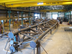
Bus Station Roof, Slough
(Image courtesy of S.H.Structures Ltd.)


[top]Introduction
In steel construction, dimensional variation is significant in a number of ways, for it involves structural steelwork manufactured remote from the site, civil engineering works at the site, and sometimes even precise mechanical components. These interface with each other and yet their precision varies from the high accuracy of mechanical components to the inaccuracies inherent in placing concrete. It is convenient to distinguish between the following:
.jpg)
(Image courtesy of Kiernan Structural Steel Ltd.)
- Mechanical fit, which is vital, for example, for functioning between nut and bolt, between bearing and girder, and between machined abutting faces of compression members.
- Fit-up of fabricated members, which is essential for efficient assembly. In a bolted site splice, for example, relative position of holes is crucial for inserting the bolts but the positional accuracy of individual bolts has very little effect on the strength of the connection.
- Deviation from flatness or straightness, which affects the stiffness and strength of components. For example, buckling resistance is less for an out-of straight slender strut.
- Accuracy of assembly at site, where the steelwork must be assembled without having to apply unintended forces to connections and without deforming the structure from its intended geometry (thus inhibiting, for example, construction of the correct concrete slab thickness).
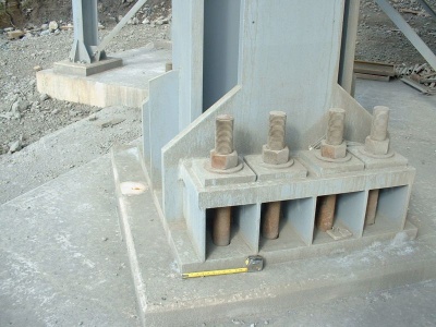
- Interface with substructures and foundations, where adjustment has to be provided to accommodate the different accuracies of steelwork and substructure – for example, the provision of large pockets for holding down bolts and variable grout layers beneath bearings and base plates.
The control of dimensions is fundamental to the mechanical engineering discipline, and without which no mechanism could work, no parts would be interchangeable. It is achieved by specifying tolerances – limits to the deviation from nominal dimension. No mechanical drawing is complete without tolerances on all dimensions, limits and fits on mating parts, and flatness tolerances on surfaces. In contrast, civil engineering construction has largely ignored the concept of tolerances, depending on the calibration of its metrology to build the product satisfactorily in situ. Historically, steel fabrication found a workable compromise, making large manufactured products using workshop techniques that assured their efficient assembly at a remote site – tolerancing was not part of that process as a rule; it was implicit in much of the work.
The level of accuracy common to a mechanical engineering workshop is generally unnecessary for constructional steelwork – for which it would have to be justified because such accuracy comes at a substantial cost and needs special facilities, including machining. For example, the variation of flatness and thickness of a steel plate from the rolling mill is perfectly satisfactory for a girder, but it would be unacceptable for a machine part. With the widespread use of automated processes from the 1980s for cutting, hole drilling, girder assembly and welding, the geometrical accuracy to which steel fabrication can be made has much improved: this has been driven by the economics of practicable manufacture and the replacement of labour intensive traditional practice.
For each new project, the steelwork contractor will assess the design to determine how best to undertake the fabrication and how to control dimensions to ensure proper fit-up and assembly at site. For large roof trusses, box girders, and for large bridges with steel decks, this may well include a project specific regime of dimensional tolerances on sub-assemblies; these would be compatible with the tolerances set by the designer for the finished building or bridge.
[top]Fabrication tolerances
Geometrical tolerances are specified in Annex B of BS EN 1090-2[1]. Tolerances are grouped three distinct categories:
- Essential tolerances. These are the limits of permissible deviation for the mechanical resistance and stability of the structure and are used to support conformity assessment to BS EN 1090-1[2].
- Functional tolerances. These are the limits of permissible deviation for fit-up and appearance. Two classes of deviation are given, class 1 being the less onerous and is the default for routine fabrication. Class 2 requires more expensive and special measures through fabrication and erection.
- Special tolerances. Individual projects may specify special tolerances, either as a modification of the essential or functional tolerances or for aspects not already covered. There is a need for certain additional tolerances on most bridge structures, and these should generally be implemented via the Specification for Highway Works[3]. Guidance on geometrical tolerances for bridges is available in GN5.03
The values of the permitted deviations for both essential and functional manufacturing tolerances are given in tables BS EN 1090-2[1] B.1 through to B.14. Essential and functional erection tolerances are given in Tables B.15 to B.25. As an alternative to the functional tolerances in Annex B, BS EN 1090-2[1] does allow the use of BS EN ISO 13920[4]; this is more likely to be used in cases of heavily welded structures where distortion from welding is the dominant factor in determining the dimensions and shape. That standard specifies general tolerances for linear and angular dimensions and for shape and position of welded structures.
[top]Causes of fabrication distortion

(Image courtesy of Mabey Bridge Ltd.)
Distortion is a general term used in steelwork to describe the various movements and shrinkages that take place when heat is applied in cutting or welding processes. All welding causes a certain amount of shrinkage and in some situations will also cause deformation from the original shape. Longitudinal and transverse shrinkage in many circumstances are only a minor problem but angular distortion, bowing and twisting can present considerable difficulties if the fabrication is not in experienced hands.
A full awareness of distortion is vital to all concerned with welding including the designer, detailer, factory foreman and the welders, as each in their actions could cause difficulties through lack of understanding and care. Weld sizes should be kept to the minimum required for the design in order to reduce distortional effects; in many cases, partial penetration welds can be used in preference to full penetration welds, deep penetration welds in preference to ordinary fillet welds.
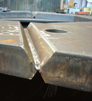
Some distortional effects can be corrected, but it is much more satisfactory to plan to avoid distortion and thereby avoid the difficulties and costs of straightening and flattening to achieve final acceptability. Consider a single fillet weld making a ‘T’ joint, as shown below. On cooling, the weld metal will induce a longitudinal contraction, a transverse contraction and an angular distortion of the up-standing leg. A similar section with double fillet weld will induce greater longitudinal and transverse contraction and the combined forces will produce an angular distortion or bowing of the table of the Tee. The longitudinal shrinkage is likely to be about 1 mm per 3 m of weld and transverse contraction about 1 mm, provided the leg length of the weld does not exceed three quarters of the plate thickness.
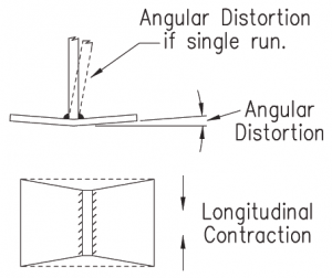

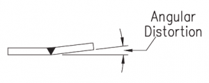
The contractions produced by a single V butt weld(see below) induce longitudinal and transverse shrinkage, producing angular distortion and possibly some bowing. The transverse contraction will be between 1.5 mm and 3 mm and the longitudinal contraction about 1 mm in 3 m. Angular distortion occurs after the first run of weld cools, contracts and draws the plates together. The second run has the same shrinkage effect but its contraction is restricted by the solidified first run, which acts as a fulcrum for angular distortion. Subsequent runs increase the effect. The angular distortion is a direct function of the number of filler runs and not the plate thickness, although of course the two are related.

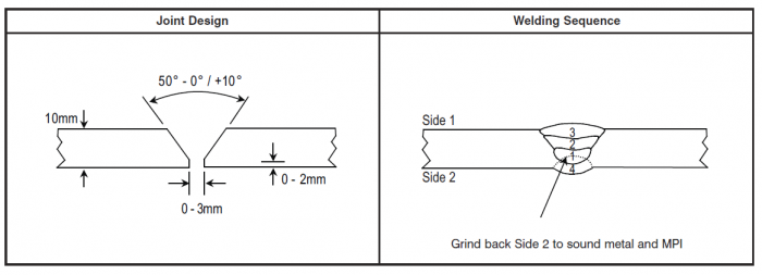
The use of a double V preparation to balance the volume of weld about the centre of gravity of the section will significantly reduce any angular distortion. To allow for the effect of back gouging, asymmetric preparations are often used to advantage, but it must be remembered that longitudinal and transverse contractions will still be present.

The contractions in a structure can be assessed, but a number of factors will affect the result. The fit-up is most important, as any excess gap will affect the weld volume and increase shrinkage. The largest size of electrodes should be used and where possible semi-automatic and automatic processes should be employed, to reduce the total heat input and the shrinkage to a minimum.
It is always worth considering the effects of weld preparation on quality of the weld, Single V butt welds give good access to the root of the weld and can limit the amount of positional work required for the welder. Double V butt welds will reduce distortion but increase the amount of positional welding, which may lead to expensive repairs. In both cases, the material thickness and process need to be assessed with an eye to practicality.


(Image courtesy of Mabey Bridge Ltd.)
In certain circumstances, residual rolling stresses in the parent metal can have considerable effect and may cause otherwise similar sections to react differently. The extent of final distortion will be a combination of the effects of inherent stresses and those introduced by welding.
Further guidance on straightening and flattening is available in GN5.07
[top]Control of distortion
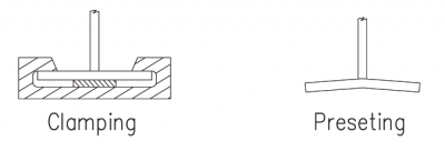

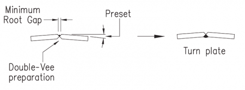
All members that are welded will shrink in their length, so each member will either be fabricated over-length and cut to length after welding, or an estimate of shrinkage will be added to anticipate the effect during the fabrication of the member. For the control of angular distortion and bowing, there are two methods of control that can be considered if the distortion is likely to be of significance (see below):
- Pre-setting. The section is bent in the opposite direction to that in which it is expected to distort and welding is then carried out under restraint. When cool, the clamps are removed and the section should spring straight. Trials and experience can determine the extent of pre-bend for any particular member.
- Clamping. The units are held straight by clamps whilst the welding is carried out, which reduces the distortion to tolerable amounts.
[top]Effect of design on distortion
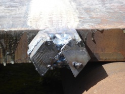
A good design will use the minimum amount of weld metal consistent with the required strength. Where a flange changes direction (for example at the end of a haunch on a bridge girder) it is preferable for the plate to be bent, rather than butt welded. Where a cross section is asymmetric, the shrinkage of the two web-to-flange welds will lead to curvature, because the shrinkage is not balanced. The steelwork contractor can allow for this but highly asymmetric arrangements, particularly with a much heavier weld to one flange, or with a flange set to one side of a web (as in a channel or J section, see below), should be avoided where possible. Where the shrinkage is balanced, only an allowance for the overall contraction needs to be made.

Weld shrinkage effects on asymmetric sections
Example of an asymmetric fabricated girder (J-section)


[top]Fabrication of girders
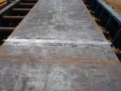
Butt joints in flanges or webs of girders are completed before the girders are assembled wherever practical. Run-on / run-off pieces are clamped at each end of these joints; alternatively, they can be tack welded on the internal face of the weld: they should be of the same thickness as the plate material and have the same weld preparation. Extension pieces are removed after the completion of the welding and the flange edges carefully dressed by grinding; any visible imperfections are normally removed at this stage and the weld repaired.
- Example of a dressed butt weld with a flush finish and run-off plates
(Images courtesy of Mabey Bridge Ltd.)


The direction of weld runs is usually alternated to avoid the tendency for the joint to distort in plan. It may be necessary to balance the welding of the butt joints by making a number of runs in one side of the V preparation and then turning the flange over to make runs in the second side and so on. Backchipping or gouging must be carried out before commencing welding on the second side. The use of suitable rotating fixtures will enable long flanges to be turned over without risk of cracking the weld.
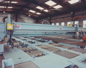

(Image courtesy of Mabey Bridge Ltd.)width
On completion of all web and flange butt joints, the girder is assembled and welded. If automatic welding is to be used for the web to flange welds, the stiffeners are added after these welds are complete. If the weld on one face is made before the weld on the other face (unlike welding in a T and I machine), the flange will be set slightly out of square to allow for the greater effect of the welding of the first side fillet welds. Where manual welding is used, it is normal practice to fit the transverse web stiffeners before the welding; these help to maintain the squareness of the flanges.
Distortion can come to the steelwork contractor’s aid where bearing stiffeners need to be fitted. Local flange heating can be used to bow the flanges locally (away from the stiffener end), allowing insertion of the stiffener; the subsequent cooling causes the flanges to come into tight contact with the stiffener end. Such controlled heat input operations are part of the fabrication art and are generally not detrimental.
[top]Site welded girder splices
Where a girder is spliced by welding (most often at site), it is usual to weld the flanges before the web; the flange, being thicker and requiring a greater number of runs of weld, will shrink more than the thinner web. (If a thin web were welded first, it would be likely to buckle as a result of flange shrinkage.) It is then necessary to anticipate this procedure by fabricating the web joint with a root gap larger than that specified by the weld procedure, by an amount equal to the expected weld shrinkage of the flange joint. In heavy girder joints, a variation of the procedure is often adopted: both flanges are completed to about two thirds of their weld volumes and then the web welds and finally the rest of the flange welds. This method helps to minimise tensile stresses remaining in the web.
[top]Checking of deviations

(Image courtesy of Mabey Bridge Ltd.)
The potential difficulty associated with working to specified tolerances is the amount of checking required in the fabrication factory. The specification of reasonable tolerances should not increase fabrication costs, as a good steelwork contractor should be able to comply with the values without special procedures or rectification measures. However, as well as the direct cost of checking, costs can be incurred when checking activities delay the work-piece from entering the next phase of production: checking adds time and cost to the overall fabrication process.
It should be noted that BS EN 1090-2[1] does not set frequencies for checking component parts: the reliance is on the steelwork contractor to have an approved Factory Production Control system (FPC) in place to maintain the quality of the finished work and set the frequencies of testing in an inspection plan for the project.
Normally, all member components are visually examined by the steelwork contractor; not all dimensions will be checked for compliance with the specified tolerances but critical dimensions and those which appear likely to be out of tolerance will be checked.
In making any checks for flatness, the scanning device is placed such that local surface irregularities do not influence the results. The checks are performed on completion of fabrication, and then at site on completion of each site joint. Local checks will be made on flatness of plate panels and straightness of stiffeners.
The verticality of webs at supports can only be checked during any trial erection of the steelwork or after erection at site. For the end supports of bridges with a skew of more than about 30°, significant twist of the girders is likely to occur when weight of the slab is applied. This arises from the displacement of the bracing. In such cases, the designer should either specify that the webs are vertical before concreting or supply values for the predicted twist so that the steelwork contractor can preset the girders to counteract it (though precise prediction is always difficult and it cannot be guaranteed that the girder will twist back to within required verticality). Further guidance on the verticality of webs at supports is available in GN 7.03.
Where the geometrical tolerances specified in BS EN 1090-2[1] are exceeded, remedial actions can be taken to remove the distortion, such as by heat straightening measures. Unless exceptionally severe, such straightening does not need to be referred to the designer but it should only be carried out according to an established procedure. In some cases, where remedial work is difficult or impracticable, the designer may be asked to consider whether the actual deviation, in the particular location, is acceptable.
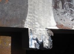
[top]Correction of distortion
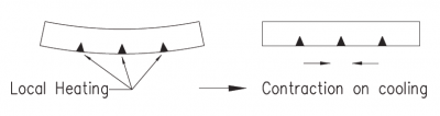

Sections can be straightened with the aid of hydraulic presses or using special bar bending or straightening machines. Some sections are too large for this type of straightening and it is necessary to adopt techniques involving the application of heat – so-called heat straightening. In this procedure, heat is applied to the face opposite to that with the welds which caused the distortion. The technique is based on the fact that if heat is applied locally to a member, the heated area will try to expand but will be constricted by the surrounding area of cold metal, which is stronger than the heated area. Upon cooling, the metal in the heated area gains strength as it shrinks, causing the member to curve, with the cooling face on the inside of the curve.
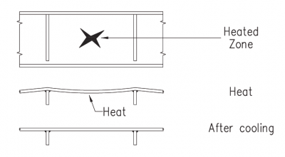
The application of heat has to be carefully controlled to prescribed temperatures and considerable experience is required before it can be successfully applied – overheating will cause metallurgical problems. The method of heat application is also used to straighten long strips of plate that have been flame cut along one edge, where release of the internal residual rolling stresses and the effect of the heat of the cut have caused curving during cutting. In this case, heat is applied in triangular areas on the edge opposite to the flame cut edge. Out-of-tolerance distortions in plate panels can also be reduced by suitable local heating of the panel, sometimes combined with jacking to provide restraint.

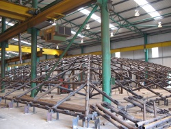
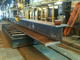
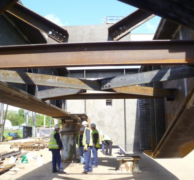
[top]Trial erection
Trial erection of bridge steelwork at the fabrication works has been a traditional way of ensuring that fit-up and geometry can be achieved at site, so reducing the risk of delays in erection or damage to protective treatment. With the much-improved accuracy achieved by automated fabrication procedures, the need for trial erection has been much reduced. Today, trial erection of most bridges is unnecessary and indeed complete trial erection of a large structure may be impracticable. However, where a delay in assembly at site due to mis-fitting components would cause unacceptable delays or consequences, or remedial measures would be extremely difficult, trial erection is of considerable benefit. This is particularly true for a railway or highway bridge that is to be erected during a limited possession.
Partial trial erection involving complex or close fitting connections, such as in skewed integral crossheads or the shear plate connections of the standard rail underbridge box girders, is also justifiable. This may also enable the steelwork contractor to position or adjust and weld some components of the connection, such as end plates, during the trial erection, as a practical way of achieving fit-up.
The extent of any trial erection should be considered carefully, bearing in mind that simultaneous trial erection of a large bridge off site may be totally impracticable. Full trial erection is inevitably on the critical path so, apart from the substantial costs, it adds considerable time to the fabrication programme. If a multiple span bridge is to be trial erected, partial or staged trial erections may be appropriate and will depend upon the amount of space which the steelwork contractor has available. Depending upon the degree of repetition and the fabrication methodology, trial erection of a particular span only may be sufficient. Often the need for full trial erection can be reduced or dispensed with once the early stages of erection have successfully been proved.
The designer, in considering the need for trial erection needs to evaluate the risks and consequences of delay at site – who would be most at risk, is it worth the client in effect paying a large premium for assurance for the risk involved? For his part, the experienced steelwork contractor will plan his fabrication, fit-up and checking procedures to minimise the risk to himself and the project.
In addition there may be significant advantages to be gained from trial erection of complex steelwork interfacing with other building components. This step was taken on Heathrow Terminal 5 where a whole bay was trial erected and many interface issues were resolved during the trial. Also, during that step, potential safety risks to erectors and others can be identified and reduced or avoided by re-engineering the access arrangements, for instance.
Further guidance on trial erection is available in GN 7.04
- Examples of trial erections
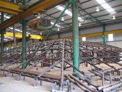
Workhouse Square, Mcdonagh Station, Kilkenny
(Image courtesy of S.H.Structures Ltd.)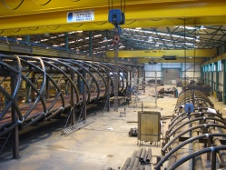
M8 Footbridge, Harthill
(Image courtesy of S.H.Structures Ltd.)
Bus Station Roof, Slough
(Image courtesy of S.H.Structures Ltd.)
[top]References
- ↑ 1.0 1.1 1.2 1.3 1.4 BS EN 1090-2:2018, Execution of steel structures and aluminium structures. Technical requirements for steel structures, BSI
- ↑ BS EN 1090-1:2009+A1:2011, Execution of steel structures and aluminium structures. Requirements for conformity assessment of structural components, BSI
- ↑ Manual of Contract Documents for Highway Works (MCHW). Volume 1: Specification for Highway Works. Series 1800 Structural Steelwork. April 2021, TSO
- ↑ BS EN ISO 13920:1997, Welding. General tolerances for welded constructions. Dimensions for lengths and angles. Shape and position, BSI
[top]Resources
- National Structural Steelwork Specification (6th Edition), Publication No. 57/17, BCSA 2017
- Steel Bridges: A practical approach to design for efficient fabrication and construction, 2010, (Publication no. 51/10), BCSA
- Hendy, C.R.; Iles, D.C. (2015) Steel Bridge Group: Guidance Notes on best practice in steel bridge construction (6th Issue). (P185). SCI