Moberly Leisure Centre and Prime Place, Kensal Rise, London
Article in NSC May 2017
Trusses span sporting haven
A series of storey-high trusses create the transfer deck between a leisure centre and a residential scheme in London.
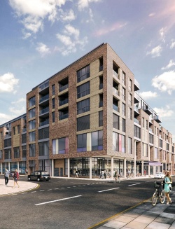
Replacing a number of old Victorian buildings, North Westminster will soon have a new community sports centre offering an array of leisure facilities including two pools and an eight-court badminton hall. Known as the Moberly Leisure Centre, the project, which is currently under construction in Kensal Rise, west London, also includes a substantial residential element known as Prime Place, which consists of 56 rooftop apartments and 15 townhouses.
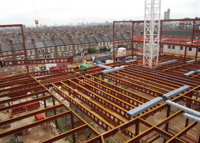
Steelwork is playing a central role in the job as the leisure centre is a large steel-framed structure that supports the light gauge steel-framed apartments above. Explaining why a steel solution was chosen for the project’s design, AECOM Principal Engineer Lloyd Bickle says: “We needed long spans for the sports areas and steel cellular beams offered the most efficient solution. Meanwhile, parts of the roof need to act as a transfer structure spanning over the relatively large open areas of the leisure centre to support the load bearing walls of the apartments above. Steel trusses can span these distances picking up the required load with the necessary stiffness.”
Work on the project began during April last year (2016) with main contractor Willmott Dixon removing a large amount of asbestos, prior to demolishing the existing buildings and clearing the site.
Steelwork erection kicked off towards the end of last year, and has progressed in a sequential manner starting at the southern end of the site. Explaining why this sequence was necessary, Willmott Dixon Construction Manager Stuart Rooney says: “When the steelwork erection began, we were still doing groundworks as well as pouring the concrete for the basement and pool areas on the north side of the site. Working this way kept the project on schedule.”
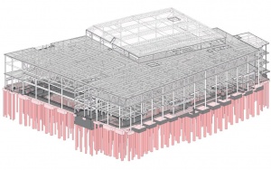
The leisure centre is a two-storey structure, albeit with a 9m-high floor-to-ceiling height in most areas. It is a large braced frame with bracing located along elevations and within the core areas. Interestingly, all of the leisure centre’s main cores were changed from concrete to steel in order to speed up the programme.
The ground floor area contains a 25m-long six-lane swimming pool, a learner pool with a moveable floor, a multi-use hall for boxing and gymnastics, changing rooms and a café, as well as the main entrance and reception. This floor also includes a mezzanine level which will accommodate community and meeting rooms.
One part of the scheme, positioned along the main Chamberlayne Road elevation, is however a separate and independent steel frame. Containing a 225m2 retail unit with two apartments above, this area has been designed as an independent structure so that it can be isolated from the leisure centre’s adjoining first floor gym to mitigate any potential acoustic transfer. As well as the gym, the first floor of the leisure centre contains three exercise/dance studios and an eight-court sports hall with seating for 500 spectators.
Westok cellular beams have been installed to form the long span column-free areas on the ground and first floors. Spanning the pools and the gymnastics hall, a series of 15.3m-long × 900mm-deep beams, each weighing 2.3t, has been used. Spanning the first floor sports hall, and forming part of the leisure centre’s roof, is a series of 38m-long × 1.261m-deep beams, each weighing 15t. These beams are cranked at both ends to form a feature mansard roof.
The long span areas of the project are all centrally-positioned within the overall scheme. Forming an L-shape around these areas and extending along the two main elevations on Chamberlayne Road to the west and Kilburn Lane to the north, the steel frame is formed by a more traditional beam and column structure. This part of the structure accommodates changing rooms and other facilities that do not need large open-plan spaces.
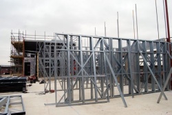
Above this L-shaped part of the structure sit the project’s light gauge steel-framed apartments and their roof gardens. The units are a mixture of one and two-bedroom apartments, containing either one or two bathrooms. Rising to a maximum height of four levels, the apartments are in a stepped formation falling to a single level of units in the south and east of the project.
There are 30 different configurations of apartment and consequently their column lines seldom match the regular 6m × 6m column grid pattern in the leisure centre. As well as the light gauge framework, a total of 30t of hot-rolled steel columns have been used to form the apartments.
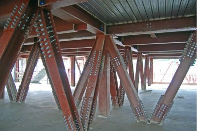
To support the irregular light steel frames, a transfer structure has been designed to sit between the leisure centre and the residences. Formed with a series of 4.6m-deep trusses, they vary in length, with the longest measuring 19m and weighing 14t. The deep trusses also create useable space within their depth, a de-facto second floor of the leisure centre, where plant equipment will be accommodated.
“The majority of the project’s steelwork was erected using the site’s two tower cranes, but the trusses were too heavy and had to be installed using a 350t-capacity mobile crane,” says Mifflin Construction Project Director Nigel Jones. The trusses had to be brought to site in small sections and then assembled on the ground, with each one requiring nearly 1,000 bolts.
The majority of the project’s steelwork will not be on view within the completed scheme. The only exceptions are the cellular beams and a series of perimeter CHS columns that form the two main elevations beneath the apartments.
The project is due to be complete by Spring 2018.
Transfer trusses
By David Brown, SCI
The steel trusses used at the Moberly leisure centre are storey height Warren trusses, carrying plant loading in addition to the apartments above. The development of the truss solution illustrates some of the design aspects to be carefully considered. Design loading might be thought to be straightforward, but in reality can often be a moving target as the design develops. At Moberly leisure centre, the flexibility of a steel solution meant that the final solution of apartments above could be revised, but this also meant that the loads were changing – perhaps a common challenge in the fast-moving world.
Deflection is always important in every structure and often checked under variable actions only. With transfer trusses, the deflection due to permanent actions may have a significant effect on the supported structural elements and so is a situation to be carefully investigated. At the leisure centre, the impact of the construction programme had to be considered, as some construction was proceeding prior to all the permanent loads being applied to the trusses. The fit-out below the trusses was to be completed before the apartments above were erected, so details to accommodate the anticipated deflection had to be incorporated in the fit-out below the trusses.
Given the span and depth of the trusses, welded pre-fabrication in sections and bolted assembly on site was necessary, as would be the case for all very large elements. Design and detailing should be then affected by the need to bolt sections together – a typical first choice is to provide end plate type splices at a node point in the compression chord (at a location also restrained out of plane), and cover plate type splices in the tension chord. This assumes that reversal will not take place – which is unlikely with apartments on top of the trusses. Generally, pre-loaded assemblies are likely to be used in the tension splices to avoid any unexpected additional deflection.
The trusses at the Moberly leisure centre were analysed assuming pinned joints, which is to be recommended for simplicity. Even without applied moments, the joints in a transfer truss will probably involve considerable local strengthening. If the truss members (including the internals) are UC sections, a good starting position is to consider that the axial load in an element is in proportion to the cross sectional area. A single UC flange will therefore be carrying approximately 40% of the axial load in the member, and it can be helpful to consider how this load is transferred to the chord. As the flange of the internal member is generally perpendicular to the web of the chord, local strengthening is probably inevitable.
A longer discussion on the use of trusses appears in the March issue of NSC
| Architect | Roberts Limbrick |
| Structural Engineer | AECOM |
| Steelwork Contractor | Mifflin Construction |
| Main Contractor | Willmott Dixon |
| Main Client | Westminster City Council / Prime Place |


